|
SPC
Version 0.9.5
|
|
SPC
Version 0.9.5
|
This variable allows control over the 6 strobe lines.
| D31-D6 | D5 | D4 | D3 | D2 | D1 | D0 |
|---|---|---|---|---|---|---|
| - | WR | RD | S3 | S2 | S1 | S0 |
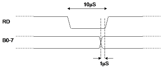
There are 4 general purpose outputs, S0 - S3. These 4 lines may be used as digital outputs. There are 2 special purpose outputs, RD and WR. These lines are automatically activated when DigitalIn is read or DigitalOut is written. When DigitalIn is read, the RD output will pulse for about 10 S. If the StrobeControl RD bit is 0, the RD output will pulse high, if the bit is 1, the output will pulse low.

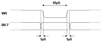
The timing for a read. An external device which is relying on the RD strobe output for synchronizing with the SuperPro hardware may use the leading edge of the RD strobe to present data on B0 - B7. The device must have the data ready within 9 microseconds of the start (leading edge) of the RD strobe. The timing for a write.

An external device which is relying on the WR strobe output for synchronizing with the SuperPro hardware may use the leading edge of the WR strobe as either an edge type clock or a latch type due to the data being presented on B0 - B7 at least 1 microsecond before the strobe is active until 1 microsecond after.

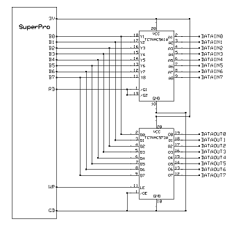
In a typical example of using the strobes to use the B0-7 bus bi-directionally: